Home » Gear pump
Industrial Gear Pumps
Callisto gear pumps are well suited for the transfer of viscous and semi viscous fluid for the following industries
& applicaƟons:
» Hydrocarbon transfer, Loading, Unloading & metering such as Fuel oils, Gas Oils & Diesel fuels & Bio diesels
» Small scale hot oil circulation system
» Dye, Paint & Pigment production & Transfer
» Tar, Bitumen & Aspault production and transfer
» Resin and polymer transfer
» Adhesives and filters
» Viscous and semi viscous lubricaƟng fluid producƟon and transfer
Thanks to our broad and extensive experience as well as hi-tech R&D facilities, we are able to produce bespoke
systems and pumps to specifically match cutomer requirements in a range of materials and sizes.
and benifits:
» Accurate and pulseless flow at high differential pressure
» Ability to pumps fluids too viscous for centrifugal pumps
» High differential pressure than centrifugal pumps
» High mechanical efficiency across different pressures and varying flow
» Efficient suction lift applications
» Ability to operate at different points on their curves as flow is proportional to rotational speed and pressure is
dependent on the installed motor power.
» Bi-directional pumping action.
» Suitable for safe area & ATEX rated/ Hazadous application
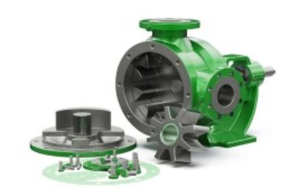
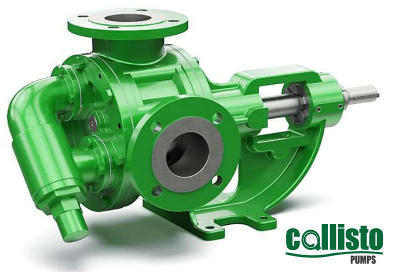
Internal Eccentric Gear Pumps
Connection sizes
: 0.1 – 250 m3/hr
Cast steel/ Stainless steel AISI 304/
Stainless steel SS316
SS304/ SS316 / CrNi stainless steel/
SnBz12 Bronze
Hard metal coated steel
Rotatherm seal/ Lip seal/
Mechanical seal / Cartridge type
Mechanical seal
| Model | Max flow, m3/hr> | Max pressure, Bar | Viscosity range, cSt | Max speed (Rpm) | Max temperature (Deg c) |
|---|---|---|---|---|---|
| CMZ 3/4 | 0.4 | 15 | 10 – 1,650 | 1400 | 100 |
| CMZ 1/2 | 0.8 | 15 | 10 – 1,650 | 1400 | 100 |
| CMZ 1 | 2 | 10 | 10 – 1,650 | 1400 | 120 |
| CMZ 1-1/2 | 5.7 | 12 | 10 – 1,650 | 1400 | 200 |
| CMZU 1-1/2 | 6.7 | 12 | 10 – 1,650 | 1400 | 200 |
| CMZ 2 | 9 | 12 | 10 – 1,650 | 1400 | 200 |
| Bareshaft Units with 90º Connections for Higher Viscosity Fluids & Medium Pressures |
|---|
| CP 1 | 3 | 7 | 10 – 55,000 | 1400 | 100 |
| CP 1-1/2 | 5.5 | 7 | 10 – 55,000 | 1400 | 100 |
| Heavy Duty Bareshaft Units for Higher Viscosity Fluids, Flows & Pressures |
|---|
| CZ 1 | 3 | 14 | 10 – 55,000 | 1400 | 200 |
| CZ 1-1/2 | 6 | 14 | 10 – 55,000 | 1400 | 200 |
| CZU 1-1/2 | 7 | 14 | 10 – 55,000 | 1400 | 200 |
| CZF 200 | 15 | 14 | 10 – 55,000 | 900 | 200 |
| CZZF 2 | 11.6 | 14 | 10 – 55,000 | 500 | 200 |
| CZF 2 | 15 | 14 | 10 – 55,000 | 500 | 200 |
| CZF 2-1/2 | 25.5 | 14 | 10 – 55,000 | 500 | 200 |
| CZUF 2-1/2 | 32 | 14 | 10 – 55,000 | 420 | 200 |
| CZF 3 | 32 | 14 | 10 – 55,000 | 420 | 200 |
| CZBF 3 | 55 | 14 | 10 – 55,000 | 400 | 200 |
| CZF 4 | 55 | 14 | 10 – 55,000 | 400 | 200 |
| CZYF 400 | 90 | 14 | 10 – 55,000 | 400 | 200 |
| CZBF 4 | 120 | 14 | 10 – 55,000 | 400 | 200 |
| CZF 5 | 110 | 9 | 10 – 55,000 | 280 | 200 |
| CZF 6 | 135 | 9 | 10 – 55,000 | 350 | 200 |
| CZF 8 | 200 | 14 | 10 – 55,000 | 220 | 200 |
| Close Coupled Units for Low to Medium Viscosity Fluids & Pressures |
|---|
| CMB 1 | 3 | 10 | 10 – 1,650 | 1400 | 70 |
| CMB 1-1/2 | 5.7 | 7 | 10 – 1,650 | 1400 | 70 |
| CMBF 2 | 15 | 5 | 10 – 5,500 | 500 | 70 |
| CMBF 2-1/2 | 23 | 5 | 10 – 5,500 | 450 | 70 |
| CMBUF 2-1/2 | 32 | 5 | 10 – 5,500 | 450 | 70 |
| CMBF 3 | 32 | 5 | 10 – 5,500 | 450 | 70 |
Internal eccentric gear pump direction of rotation:
Internal Eccentric Gear Pumps are generally supplied in a clockwise direction of rotation (when viewed from the drive end) meaning that the inlet is therefore at the left hand side (when looking at the pump head) and delivering out of the top. An easy way to tell which side the suction port is set up on is to look at which direction the pressure relief valve on the pump is facing. The end cap of the pressure relief valve must always point to the suction port, otherwise it will not function! The direction of rotation can be changed by switching the position of the pressure relief valve and wiring the motor to turn in the opposite.
Internal eccentric gear pump flange position:
Pump casings can be turned through 8 different orientations to enable easy installation into numerous different pipework systems. Make sure that the pressure relief valve is pointing to the suction though!
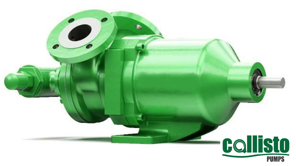
Magnetic Drive Internal Gear pumps
Connection sizes
Cast steel/ Stainless steel AISI 304/
Stainless steel SS316
SS304/ SS316 / CrNi stainless steel/
SnBz12 Bronze
Hard metal coated steel
| Model | Max flow, m3/hr> | Max pressure, Bar | Viscosity range, cSt | Max speed (Rpm) | Max temperature (Deg c) |
|---|---|---|---|---|---|
| CMG 1-1/2 | 5.7 | 12 | 10 – 5,500 | 1400 | 250 |
| CMGF 2 | 15 | 12 | 10 – 5,500 | 500 | 250 |
| CMGF 2-1/2 | 25.5 | 12 | 10 – 5,500 | 500 | 250 |
| CMGUF 2-1/2 | 32 | 12 | 10 – 5,500 | 500 | 250 |
| CMGF 3 | 32 | 12 | 10 – 5,500 | 500 | 250 |
| CMGBF 3 | 55 | 12 | 10 – 5,500 | 500 | 150 |
Internal eccentric gear pump working principle:
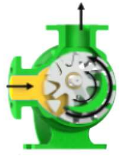
The simple “Gear within gear” principle of internal eccentric gear pumps means that there are only 2 moving components within the process medium. the posible displacement of which is achieved by the filling of the cavity between the teeth of both the rotary and ideler gears located in the pump head. With each revolution, a fixed volume of fluid, enetrs the casing through the sucƟon port, filling the space between the teeth of the gears. The crescent within the pump head then seperates the fluid as the idler gear turns on the pump shaft. The following 4 images demonstarate this operaƟon in more detail.
Fluid entering the pump:
The yellow coloured section in the image represents the process & it is entering the pump suction port, pump casing & filling the cavities between the idler gear and rotary gear. The arroes indicate the direction of the fluid passage through the pump and rotational direction of the gears.
Fluid filling the cavities & split of flow:
As the fluid progresses through the pump head and fills the cavities between the gears it is also separated by the crescent shape in the pump head, which acts as a seal preventing back flow between the suction & discharge ports.
Pump almost flooded:
As the fluid fully fills the casing all cavities between the gears are completely filled in the form of locked pockets of fluid to guarantee absolute volume control and enable the pump to deliver a fixed volume per revolution.
Pump is flooded & starts to discharge the process medium under pressure:
Once the pump is fully flooded, the rotor and idler gears mesh together and form a liquid seal which is equidistant between the pump ports which then enables the fluid to exit the discharge of the pump under pressure. The delivery pressure is dependent on the installed power of the motor.


External Gear Pumps
| Model | Max flow, m3/hr> | Max pressure, Bar | Viscosity range, cSt | Max speed (Rpm) | Max temperature (Deg c) |
|---|---|---|---|---|---|
| CMD 3/4 | 1.4 | 30 | 10 – 500 | 1500 | 100 |
| CMD 1 | 2.5 | 30 | 10 – 500 | 1500 | 100 |
| CMD 1-1/2 | 7.7 | 30 | 10 – 500 | 1500 | 100 |
| CMDY 1 | 3 | 12 | 10 – 500 | 1500 | 70 |
| CMDY 2 | 7 | 12 | 10 – 500 | 1500 | 70 |
External gear pump operating priciple:
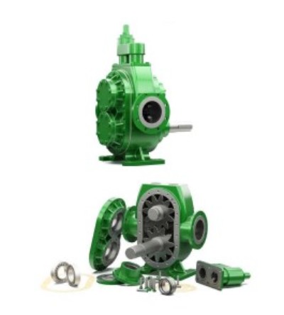
Similar in operation to the Internal Eccentric Gear Pump, again with only 2 moving components within the process medium. The positive displacement of which is achieved by the filling of the cavities between the teeth of both gears located in the pump head. With each revolution, a fixed volume of fluid, enters the casing through the suction port, filling the space between the teeth of the gears. The process medium is then carried around the periphery or external areas of the gears until the casing is fully filled with the fluid and pushed out of the pump outlet under pressure. No fluid passes between the gears.
Fluid entering the pump:
The yellow coloured section in the image represents the process medium as it is entering the pump suction port, pump casing & filling the cavities between Gears. The 3 arrows indicate the direction of fluid passage through the pump and rotational direction of the gears.
Fluid filling the cavities between the teeth of the gears & casing:
As the fluid progresses through the pump head and fills the cavities between the gears i is carried around the outside of the gears filling the casing at the top and bottom
Pump is flooded & starts to discharge the process medium under pressure:
Once the pump is fully flooded, the driving gear (Top) and driven gear (Bottom) form a liquid seal thanks to their intermeshing teeth, which then enables the fluid to exit the discharge of the pump under pressure. The delivery pressure is dependent on the installed power of the motor
Helical External Gear Pumps
| Model | Max flow, m3/hr> | Max pressure, Bar | Viscosity range, cSt | Max speed (Rpm) | Max temperature (Deg c) |
|---|---|---|---|---|---|
| CHL 2 | 12 | 10 | 10-550 | 900 | 200 |
| CHL 2-1/2 | 38 | 15 | 10 – 55,000 | 450 | 350 |
| CHL 3 | 38 | 15 | 10 – 55,000 | 450 | 350 |
| CHL 4 | 76 | 15 | 10 – 55,000 | 450 | 200 |
| CHL 8 | 250 | 15 | 10 – 55,000 | 450 | 200 |
| CHL 10 | 250 | 15 | 10 – 55,000 | 450 | 200 |


By-Bass / Pressure Relief Valve
By-Bass / Pressure Relief Valve Operation:
The intended purpose of a By- Pass or Pressure Relief Valve (PRV) is to ensure that the pump and drive unit are protected from unnecessary damage that may be incurred during over- pressurisation which is mainly caused by closed valve operation or blockages in the discharge line. By- Passes can be either installed on the pipework and route fluid back to the suction of the pump or tank, in the form of a By- Pass Circuit, or indeed installed directly on the pump head, as detailed below. The By- Pass, when opened, relieves excess fluid and pressure from the discharge section of the pump to the suction side and effectively allow the pump to recirculate within itself until the blockage in the line has been cleared or closed valve opened to allow the process medium to carry on through the system and drop the pressure in the line to an acceptable level for the installed equipment.
As By- Passes are spring- loaded and adjustable, they can be tweaked in situ to cater for changing system or pump requirements.

Heating Jackets


Installation Recommendations
Installation Recommendations :
Below are some useful installation recommendations to ensure that unnecessary damage and inconsistent performance can be avoided when using CALLISTO Gear Pumps:
* Below are some useful installation recommendations to ensure that unnecessary damage and inconsistent performance can be avoided when using Tapflo Industrial Gear Pumps.
* The diameter of the all pipework, fittings and accessories should be at least equal to or larger than the pump ports. Generally the velocity within the pipework should not exceed 2 m/s on the suction side and 3 m/s on the discharge side. Exceeding these values can result in major friction losses in the suction pipework leading to cavitation issues and high discharge pressure requirements.
* Callisto Gear Pumps are NOT solids handling, therefore, during the installation of pipework, measures must be put in place to ensure that when the pump is commissioned no particulates can enter the pump.
* Tapflo Industrial Gear Pumps are NOT solids handling, therefore, during the installation of pipework, measures must be put in place to ensure that when the pump is commissioned no particulates can enter the pump.
* If the discharge pipework is quite long, a Check Valve is also recommended to be installed so that the pressure in the line can be held by the Valve and therefore avoiding both unnecessary strain on the pump and backflow.
Suction Pipe Recommendations
Suction Pipework should be fitted tightly and installed in such a way to ensure that air pockets cannot develop during operation and damage the pump. To avoid unnecessary and excessive friction losses, suction pipework should be as short as possible with as few convolutions, sharp elbows and sudden changes in direction as possible. Avoid the above as air pockets can form in the top of the horseshoe, if absolutely necessary use horizontal elbows instead.


Maintenance & Troubleshooting
RECOMMENDED OPERATIONAL CHECKS:
Below is a list of recommended operational checks that will enable operators to extend the life of the pump and avoid
any unnecessary damage.
Regularly check the following:
* Noise, vibration and heat levels.
* Abnormal leakages.
* Flow Rates & Discharges Pressures to ensure that they are within the usual and expected ranges. Having a Flow
Meter and Suction & Discharge Pressure Gauges / Sensors are recommended.
* Elastic parts on the Coupling (if present).
* Electrical Current Draws on the motor. If higher than normal this is generally an indication of elevated discharge pressures or blockages within the pump or pipework.
OTHER RECOMMENDATIONS:
All valves on auxiliary systems should be OPEN.
* If the pump is equipped with a Packed Gland a certain amount of leakage (small drips) is expected. However, if
after prolonged periods of operation this leakage increases then tighten the nuts on the packing press until the
leakage level reverts back to normal. If the nuts are tightened fully then replace the packing gland.
* If the pump is Mechanically Sealed then no leakage should be expected. If leakage is detected then this indicates
that the mechanical seal faces have been damaged and the seal needs replacing. The lifetime of the seal is
application and usage dependent, if you are exp
| Malfunction | Possible cause | Remedy |
|---|---|---|
| No Flow whilst the pump is ON | Wrong direction of rotation Air Pockets in the Suction Line Check Valve Jammed / Blocked Insufficient Sealing on Pipework or Pump causing Air Ingress |
Reverse rotational direction by inverting wiring on motor Fill the Suction Line Manually and discharge all air left in the line Clean/Repair/Replace Check Valve Check and Seal the Suction Line & Change Pump Seal, if necessary |
| Insufficient Capacity and/or Pressure | Check Valve Jammed / Blocked Air Leakage Elevated NPSHr Pump is excessively worn Safety Valve / PRV is Open or is set too low |
Clean/Repair/ Replace Check Valve Check and Seal the Suction Line & Change Pump Seal, if necessary Shorten Length and / or Increase the ø of the Suction Pipework Reduce Manometric Suction Head Move pump closer to the fluid source Check Rotor Gear Spacing, decrease tolerance by removing Washers, if necessary Adjust Set Pressure & Check Valve Mechanism for Blockages |
| Pump is making Irregular Noise | Cavitation-Manometric Suction Head is too high Rotor/Gear Damage Pump is misaligned with Drive Assembly Vibration Noise coming from Safety Valve / PRV |
Shorten Length and / or Increase the ø of the Suction Pipework Reduce Manometric Suction Head Move pump closer to the fluid source Check Filters/Strainers on Suction Line Check Gears & change, if necessary Correct using Washers & Spacers & Laser Re-Alignment Adjust Set Pressure & Change, if necessary |
External gear pump supplier in Singapore, Internal gear pump supplier in Singapore, Magnetic seal-less gear pump supplier in Singapore, Helical gear pump supplier in Singapore
Your content goes here. Edit or remove this text inline or in the module Content settings. You can also style every aspect of this content in the module Design settings and even apply custom CSS to this text in the module Advanced settings.
