
Your content goes here. Edit or remove this text inline or in the module Content settings. You can also style every aspect of this content in the module Design settings and even apply custom CSS to this text in the module Advanced settings.
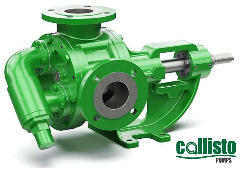
INTERNAL GEAR PUMP (CALLISTO PUMPS)
SPECIFICATIONS: Connection size : 3/8″ (to) 8″ Capacity range : 0.1 (to) 250 m3/hr Pressure range : 1 (to) 15 Bar Temperature range : Up to 200 Deg c Speed range : 20 (to) 1720 RPM Viscosity range : 20 (to) 55,000 cps Pump body & cover material : Cast iron / Spheroidal cast iron / Cast steel / SS304 / SS316 Gear material : Spheroidal cast iron / Cast steel / SS304 / SS316 / CrNi SS / SnBz12 Bronze Bearing material : Carbon graphite / Silicon carbide / Hard metal coated steel Sealing type : Soft seal/ Packing / Rotatherm seal/ Lip seal/ Mechanical seal/ Cartridge seal
Internal eccentric gear pump direction of rotation: Internal Eccentric Gear Pumps are generally supplied in a clockwise direction of rotation (when viewed from the drive end) meaning that the inlet is therefore at the left hand side (when looking at the pump head) and delivering out of the top. An easy way to tell which side the suction port is set up on is to look at which direction the pressure relief valve on the pump is facing. The end cap of the pressure relief valve must always point to the suction port, otherwise it will not function! The direction of rotation can be changed by switching the position of the pressure relief valve and wiring the motor to turn in the opposite.
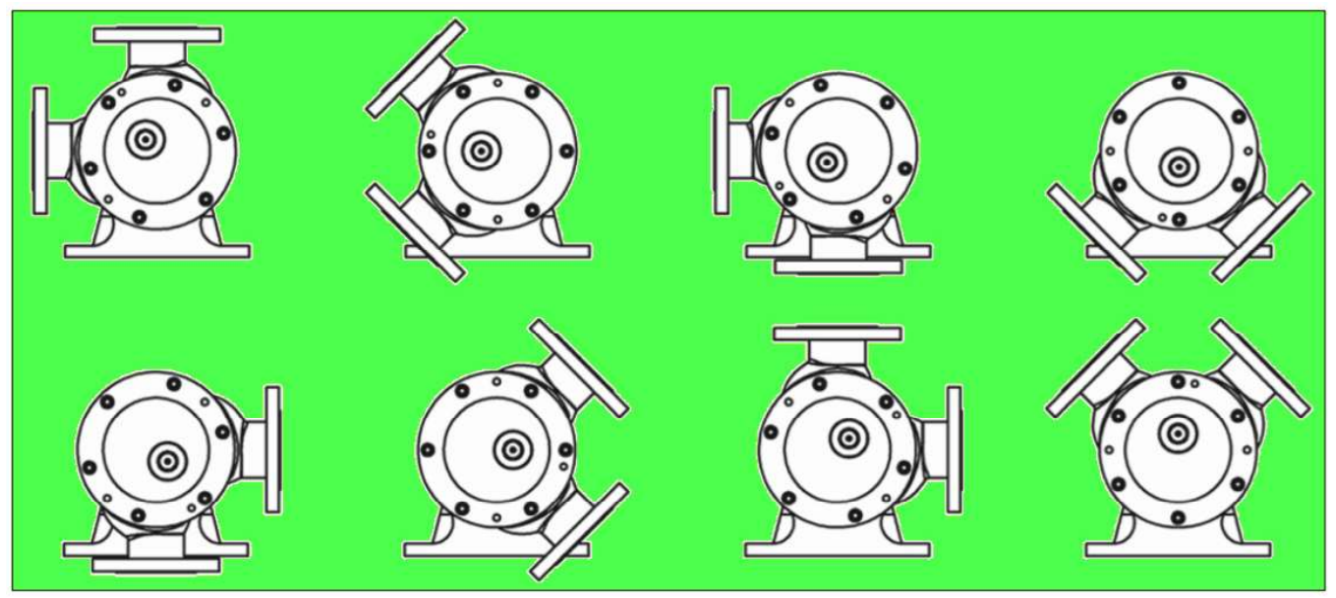
Pump casings can be turned through 8 different orientations to enable easy installation into numerous different pipework systems. Make sure that the pressure relief valve is poinƟng to the sucƟon though!
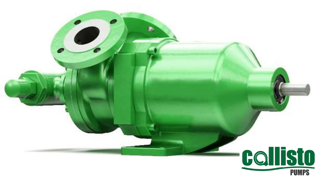
MAGNETIC DRIVE SEALLESS GEAR PUMP (CALLISTO PUMPS)
SPECIFICATIONS: Connection size : 1.5″ (to) 2.5″ Capacity range : 0.1 (to) 55 m3/hr Pressure range : 1 (to) 12 Bar Temperature range : Up to 250 Deg c Speed range : 20 (to) 1500 RPM Viscosity range : 20 (to) 5,000 cps Pump body & cover material : Cast iron / Spheroidal cast iron / Cast steel / SS304 / SS316 Gear material : Spheroidal cast iron / Cast steel / SS304 / SS316 / CrNi SS / SnBz12 Bronze Bearing material : Carbon graphite / Silicon carbide / Hard metal coated steel Sealing type : N/A
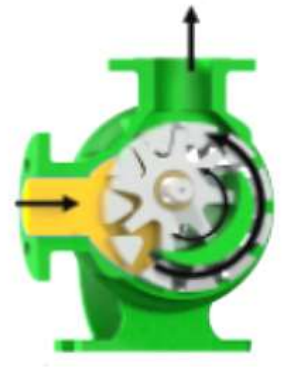
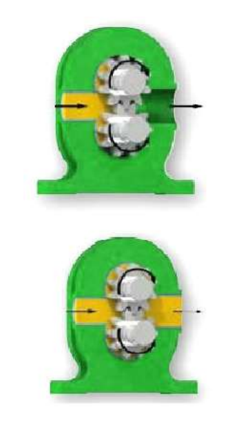
Fluid entering the pump: The yellow colored section in the image represents the process & it is entering the pump suction port, pump casing & filling the cavities between the idler gear and rotary gear. The arrows indicate the direction of the fluid passage through the pump and rotational direction of the gears.
Fluid filling the cavities & split of flow: As the fluid progresses through the pump head and fills the cavities between the gears it is also separated by the crescent shape in the pump head, which acts as a seal preventing back flow between the suction & discharge port.
Pump almost flooded: As the fluid fully fills the casing all cavities between the gears are completely filled in the form of locked pockets of fluid to guarantee absolute volume control and enable the pump to deliver a fixed volume per revolution.
Pump is flooded & starts to discharge the process medium under pressure: Once the pump is fully flooded, the rotor and idler gears mesh together and form a liquid seal which is equidistant between the pump ports which then enables the fluid to exit the discharge of the pump under pressure. The delivery pressure is dependent on the installed power of the motor.
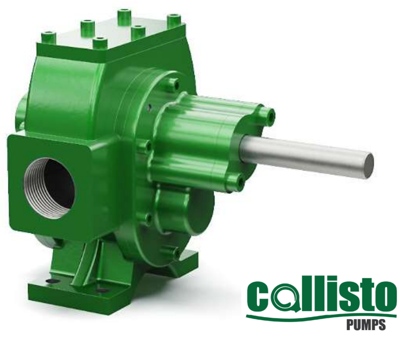
EXTERNAL GEAR PUMP (CALLISTO PUMPS)
SPECIFICATIONS: Connection size : 3/4″ (to) 2″ Capacity range : 1 (to) 7 m3/hr Pressure range : 1 (to) 30 Bar Temperature range : Up to 100 Deg c Speed range : 50 (to) 1500 RPM Viscosity range : 20 (to) 550 cps Pump body & cover material : Cast iron / Spheroidal cast iron / Cast steel / SS304 / SS316 Gear material : Spheroidal cast iron / Cast steel / SS304 / SS316 / CrNi SS / SnBz12 Bronze Bearing material : Carbon graphite / Silicon carbide / Hard metal coated steel Sealing type : Lip seal / Mechanical seal
External gear pump operating principle: Similar in operation to the internal eccentric gear pump, again with only two moving components within the process medium. The positive displacement of which is achieved by the filling of cavities between the teeth of both gears located in the pump head. With each revolution a fixed volume of fluid, enters the casing through the suction port, filling the space between the teeth of the gears. The process medium is then carried around the periphery or external areas of the gears untill the casing is fully filled with the fluid and pushed out of the pump outlet under pressure. No fluid passes between the gears.
Fluid entering the pump: The yellow color section in the image represent the process medium as it is entering the pump suction port, Pump casing & filling the cavities between the gears. The three arrows indicate the direction of fluid passage through the pump and rotational direction of the gears.
Fluid filling the cavities between the teeth of the gears & casing : As the fluid progress through the pump head and fills the cavities between the gears is carried around the outside of the gears filling the casing at the top and the bottom.
Pump is flooded & starts to discharge the process medium under pressure : Once the pump is fully flooded, the driving gear (Top) and the driven gear (Bottom) form a liquid seal thanks to their inter meshing teeth, which then enables the fluid to exit the discharge of the pump under pressure. The delivery pressure is dependent on the installed power of the motor.
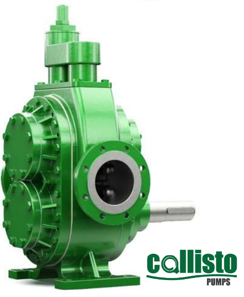
HELICAL GEAR PUMP (CALLISTO PUMPS)
SPECIFICATIONS: Connection size : 2″ (to) 10″ Capacity range : 1 (to) 320 m3/hr Pressure range : 1 (to) 15 Bar Temperature range : Up to 350 Deg c Speed range : 50 (to) 1500 RPM Viscosity range : 20 (to) 55,000 cps Pump body & cover material : Cast iron / Spheroidal cast iron / Cast steel / SS304 / SS316 Gear material : Spheroidal cast iron / Cast steel / SS304 / SS316 / CrNi SS / SnBz12 Bronze Bearing material : Carbon graphite / Silicon carbide / Hard metal coated steel Sealing type : Soft seal / Gland packing / Mechanical seal
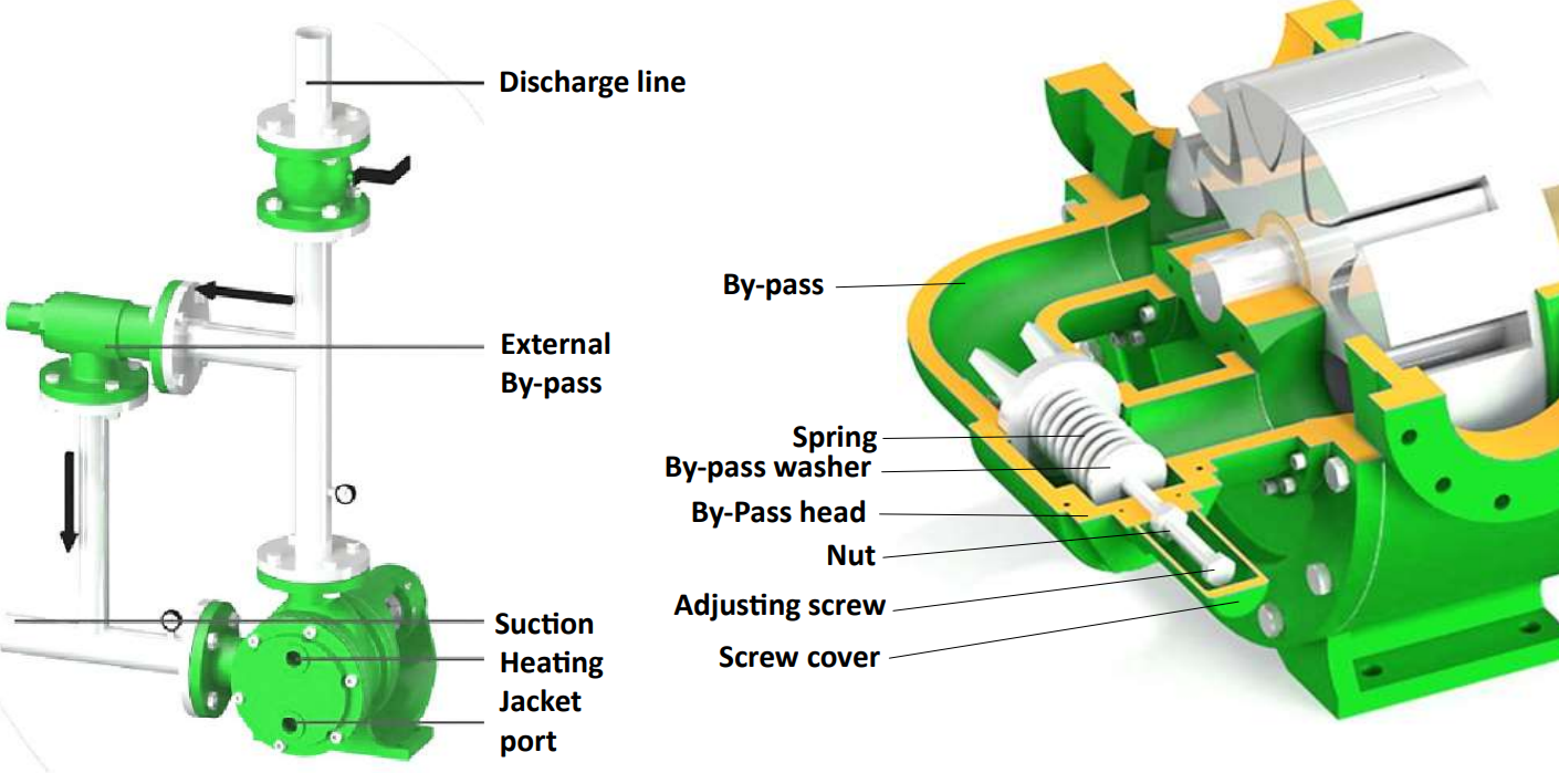
By-Bass / Pressure Relief Valve Operation: The intended purpose of a By- Pass or Pressure Relief Valve (PRV) is to ensure that the pump and drive unit are protected
from unnecessary damage that may be incurred during over- pressurization which is mainly caused by closed valve
operation or blockages in the discharge line. By- Passes can be either installed on the pipework and route fluid back to the
suction of the pump or tank, in the form of a By- Pass Circuit, or indeed installed directly on the pump head, as detailed
below. The By- Pass, when opened, relieves excess fluid and pressure from the discharge secƟon of the pump to the
suction side and effectively allow the pump to recirculate within itself until the blockage in the line has been cleared or
closed valve opened to allow the process medium to carry on through the system and drop the pressure in the line to an
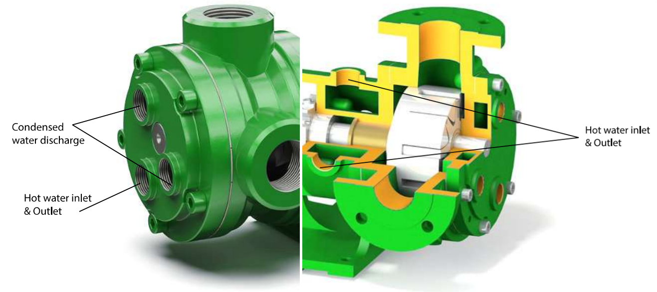
acceptable level for the installed equipment. Heating Jacket: Heating jackets are used when the process fluid temperature needs to be maintained. Callisto gear pumps can be fitted with these fitted to the front cover alone or on the bearing jackets as well double jacketed. Existing units can also be upgraded to have a heating jackets fitted to the front cover by simple cover change. The top ports are the hot
